블로그 이미지
Leeway is... the freedom that someone has to take the action they want to or to change their plans.
maetel

Notice

Recent Post

Recent Comment

Recent Trackback

Archive

calendar

1 2 3 4
5 6 7 8 9 10 11
12 13 14 15 16 17 18
19 20 21 22 23 24 25
26 27 28 29 30 31
  • total
  • today
  • yesterday

Category

2011. 1. 17. 01:21 Computer Vision
Shai Avidan, Ariel Shamir, Seam Carving for Content-Aware Image Resizing, SIGGRAPH, 2007


posted by maetel
2010. 11. 11. 16:22 Computer Vision
Image Processing for Computer Graphics and Vision, 2nd ed. 
Velho, Luiz, Frery, Alejandro C., Gomes, Jonas
Springer, 2009


비록 학부 4학년은 아니었더라도 석사 1학기에 봤었다면 좋았을 것을...


'Computer Vision' 카테고리의 다른 글

Winsock  (0) 2010.11.26
camera Firefly (FFMV-03M2M)  (0) 2010.11.25
Duda, Hart & Stork [Pattern Classification] (2nd ed)  (0) 2010.11.11
OpenCV 2.1.0 Installation on Mac OS X Snow Leopard  (0) 2010.11.02
OpenCV: Decision Trees  (0) 2010.10.12
posted by maetel
2010. 2. 10. 15:47 Computer Vision
Seong-Woo Park, Yongduek Seo, Ki-Sang Hong: Real-Time Camera Calibration for Virtual Studio. Real-Time Imaging 6(6): 433-448 (2000)
doi:10.1006/rtim.1999.0199

Seong-Woo Park, Yongduek Seo and Ki-Sang Hong1

Dept. of E.E. POSTECH, San 31, Hyojadong, Namku, Pohang, Kyungbuk, 790-784, Korea


Abstract

In this paper, we present an overall algorithm for real-time camera parameter extraction, which is one of the key elements in implementing virtual studio, and we also present a new method for calculating the lens distortion parameter in real time. In a virtual studio, the motion of a virtual camera generating a graphic studio must follow the motion of the real camera in order to generate a realistic video product. This requires the calculation of camera parameters in real-time by analyzing the positions of feature points in the input video. Towards this goal, we first design a special calibration pattern utilizing the concept of cross-ratio, which makes it easy to extract and identify feature points, so that we can calculate the camera parameters from the visible portion of the pattern in real-time. It is important to consider the lens distortion when zoom lenses are used because it causes nonnegligible errors in the computation of the camera parameters. However, the Tsai algorithm, adopted for camera calibration, calculates the lens distortion through nonlinear optimization in triple parameter space, which is inappropriate for our real-time system. Thus, we propose a new linear method by calculating the lens distortion parameter independently, which can be computed fast enough for our real-time application. We implement the whole algorithm using a Pentium PC and Matrox Genesis boards with five processing nodes in order to obtain the processing rate of 30 frames per second, which is the minimum requirement for TV broadcasting. Experimental results show this system can be used practically for realizing a virtual studio.


전자공학회논문지 제36권 S편 제7호, 1999. 7 
가상스튜디오 구현을 위한 실시간 카메라 추적 ( Real-Time Camera Tracking for Virtual Studio )   
박성우 · 서용덕 · 홍기상 저 pp. 90~103 (14 pages)
http://uci.or.kr/G300-j12265837.v36n07p90

서지링크     한국과학기술정보연구원
가상스튜디오의 구현을 위해서 카메라의 움직임을 실시간으로 알아내는 것이 필수적이다. 기존의 가상스튜디어 구현에 사용되는 기계적인 방법을 이용한 카메라의 움직임 추적하는 방법에서 나타나는 단점들을 해결하기 위해 본 논문에서는 카메라로부터 얻어진 영상을 이용해 컴퓨터비전 기술을 응용하여 실시간으로 카메라변수들을 알아내기 위한 전체적인 알고리듬을 제안하고 실제 구현을 위한 시스템의 구성 방법에 대해 다룬다. 본 연구에서는 실시간 카메라변수 추출을 위해 영상에서 특징점을 자동으로 추출하고 인식하기 위한 방법과, 카메라 캘리브레이션 과정에서 렌즈의 왜곡특성 계산에 따른 계산량 문제를 해결하기 위한 방법을 제안한다.


Practical ways to calculate camera lens distortion for real-time camera calibration
Pattern Recognition, Volume 34, Issue 6, June 2001, Pages 1199-1206
Seong-Woo Park, Ki-Sang Hong


generating virtual studio


Matrox Genesis boards
http://www.matrox.com/imaging/en/support/legacy/

http://en.wikipedia.org/wiki/Virtual_studio
http://en.wikipedia.org/wiki/Chroma_key

camera tracking system : electromechanical / optical
pattern recognition
2D-3D pattern matches
planar pattern


feature extraction -> image-model matching & identification -> camera calibration
: to design the pattern by applying the concept of cross-ratio and to identify the pattern automatically


영상에서 찾아진 특징점을 자동으로 인식하기 위해서는 공간 상의 점들과 영상에 나타난 그것들의 대응점에 대해서 같은 값을 갖는 성질이 필요한데 이것을 기하적 불변량 (Geometric Invariant)이라고 한다. 본 연구에서는 여러 불변량 가운데 cross-ratio를 이용하여 패턴을 제작하고, 영상에서 불변량의 성질을 이용하여 패턴을 자동으로 찾고 인식할 수 있게 하는 방법을 제안한다.


Tsai's algorithm
R. Y. Tsai, A Versatile Camera Calibration Technique for High Accuracy 3-D Maching Vision Metrology Using Off-the-shelf TV Cameras and Lenses. IEEE Journal of Robotics & Automation 3 (1987), pp. 323–344.

direct image mosaic method
Sawhney, H. S. and Kumar, R. 1999. True Multi-Image Alignment and Its Application to Mosaicing and Lens Distortion Correction. IEEE Trans. Pattern Anal. Mach. Intell. 21, 3 (Mar. 1999), 235-243. DOI= http://dx.doi.org/10.1109/34.754589

Lens distortion
Richard Szeliski, Computer Vision: Algorithms and Applications: 2.1.6 Lens distortions & 6.3.5 Radial distortion

radial alignment constraint
"If we presume that the lens has only radial distortion, the direction of a distorted point is the same as the direction of an undistorted point."

cross-ratio  http://en.wikipedia.org/wiki/Cross_ratio
: planar projective geometric invariance
 - "pencil of lines"
http://mathworld.wolfram.com/CrossRatio.html
http://homepages.inf.ed.ac.uk/rbf/CVonline/LOCAL_COPIES/MOHR_TRIGGS/node25.html
http://www.cut-the-knot.org/pythagoras/Cross-Ratio.shtml
http://web.science.mq.edu.au/~chris/geometry/


pattern identification

 카메라의 움직임을 알아내기 위해서는 공간상에 인식이 가능한 물체가 있어야 한다. 즉, 어느 위치에서 보더라도 영상에 나타난 특징점을 찾을 수 있고, 공간상의 어느 점에 대응되는 점인지를 알 수 있어야 한다.

패턴이 인식 가능하기 위해서는 카메라가 어느 위치, 어느 자세로 보던지 항상 같은 값을 갖는 기하적 불변량 (Geometric Invariant)이 필요하다.

Coelho, C., Heller, A., Mundy, J. L., Forsyth, D. A., and Zisserman, A.1992. An experimental evaluation of projective invariants. In Geometric invariance in Computer Vision, J. L. Mundy and A. Zisserman, Eds. Mit Press Series Of Artificial Intelligence Series. MIT Press, Cambridge, MA, 87-104.


> initial identification process
extracting the pattern in an image: chromakeying -> gradient filtering: a first-order derivative of Gaussian (DoG) -> line fitting: deriving a distorted line (that is actually a curve) equation -> feature point tracking (using intersection filter)


R1x = 0


http://en.wikipedia.org/wiki/Difference_of_Gaussians


real-time camera parameter extraction

이상적인 렌즈의 optical axis가 영상면에 수직이고 변하지 않는다고 할 때, 영상 중심은 카메라의 줌 동작 동안 고정된 값으로 계산된다. (그러나 실제 렌즈의 불완전한 특성 때문에 카메라의 줌 동작 동안 영상 중심 역시 변하게 되는데, 이 변화량은 적용 범위 이내에서 2픽셀 이하이다. 따라서 본 연구에서는 이러한 변화를 무시하고 이상적인 렌즈를 가정하여 줌동작에 의한 영상 중심을 구하게 된다.)

For zoom lenses, the image centers vary as the camera zooms because the zooming operation is executed by a composite combination of several lenses. However, when we examined the location of the image centers, its standard deviation was about 2 pixels; thus we ignored the effect of the image center change.


calculating lens distortion coefficient

Zoom lenses are zoomed by a complicated combination of several lenses so that the effective focal length and distortion coefficient vary during zooming operations.

When using the coplanar pattern with small depth variation, it turns out that focal length and z-translation cannot be separated exactly and reliably even with small noise.

카메라 변수 추출에 있어서 공간상의 특징점들이 모두 하나의 평면상에 존재할 때는 초점거리와 z 방향으로의 이동이 상호 연관 (coupling)되어 계산값의 안정성이 결여되기 쉽다.


collinearity

Collinearity represents a property when the line in the world coordinate is also shown as a line in the image. This property is not preserved when the lens has a distortion.


Once the lens distortion is calculated, we can execute camera calibration using linear methods.


filtering

가상 스튜디오 구현에 있어서는 시간 지연이 항상 같은 값을 가지게 하는 것이 필수적이므로, 실제 적용에서는 예측 (prediction)이 들어가는 필터링 방법(예를 들면, Kalman filter)은 사용할 수가 없었다.

averaging filter 평균 필터


Orad  http://www.orad.co.il

Evans & Sutherland http://www.es.com


posted by maetel
2009. 11. 8. 16:31 Computer Vision
Branislav Kisačanin & Vladimir Pavlović & Thomas S. Huang
Real-Time Vision for Human-Computer Interaction
(RTV4HCI)
Springer, 2005
(google book's overview)

2004 IEEE CVPR Workshop on RTV4HCI - Papers
http://rtv4hci.rutgers.edu/04/


Computer vision and pattern recognition continue to play a dominant role in the HCI realm. However, computer vision methods often fail to become pervasive in the field due to the lack of real-time, robust algorithms, and novel and convincing applications.

Keywords:
head and face modeling
map building
pervasive computing
real-time detection

Contents:
RTV4HCI: A Historical Overview.
- Real-Time Algorithms: From Signal Processing to Computer Vision.
- Recognition of Isolated Fingerspelling Gestures Using Depth Edges.
- Appearance-Based Real-Time Understanding of Gestures Using Projected Euler Angles.
- Flocks of Features for Tracking Articulated Objects.
- Static Hand Posture Recognition Based on Okapi-Chamfer Matching.
- Visual Modeling of Dynamic Gestures Using 3D Appearance and Motion Features.
- Head and Facial Animation Tracking Using Appearance-Adaptive Models and Particle Filters.
- A Real-Time Vision Interface Based on Gaze Detection -- EyeKeys.
- Map Building from Human-Computer Interactions.
- Real-Time Inference of Complex Mental States from Facial Expressions and Head Gestures.
- Epipolar Constrained User Pushbutton Selection in Projected Interfaces.
- Vision-Based HCI Applications.
- The Office of the Past.
- MPEG-4 Face and Body Animation Coding Applied to HCI.
- Multimodal Human-Computer Interaction.
- Smart Camera Systems Technology Roadmap.
- Index.


RTV4HCI: A Historical Overview
Matthew Turk (mturk@cs.ucsb.edu)
University of California, Santa Barbara
http://www.stanford.edu/~mturk/
http://www.cs.ucsb.edu/~mturk/

The goal of research in real-time vision for human-computer interaction is to develop algorithms and systems that sense and perceive humans and human activity, in order to enable more natural, powerful, and effective computer interfaces.

Computers in the Human Interaction Loop (CHIL)

perceptual interfaces
multimodal interfaces
post-WIMP(windows, icons, menus, pointer) interfaces

implicit user awareness or explicit user control

The user interface
- the software and devices that implement a particular model (or set of models) of HCI

Computer vision technologies must ultimately deliver a better "user experience".

B Shneiderman, Designing the User Interface: Strategies for Effective Human-Computer Interaction, Third Edition, Addison-Wesley, 1998.
: 1) time to learn 2) speed of performance 3) user error rates 4) retention over time 5) subjective satisfaction

- Presence and location (Face and body detection, head and body tracking)
- Identity (Face recognition, gait recognition)
- Expression (Facial feature tracking, expression modeling and analysis)
- Focus of attention (Head/face tracking, eye gaze tracking)
- Body posture and movement (Body modeling and tracking)
- Gesture (Gesture recognition, hand tracking)
- Activity (Analysis of body movement)

eg.
VIDEOPLACE (M W Krueger, Artificial Reality II, Addison-Wesley, 1991)
Magic Morphin Mirror / Mass Hallucinations (T Darrell et al., SIGGRAPH Visual Proc, 1997)

Principal Component Analysis (PCA)
Linear Discriminant Analysis (LDA)
Gabor Wavelet Networks (GWNs)
Active Appearance Models (AAMs)
Hidden Markov Models (HMMs)

Identix Inc.
Viisage Technology Inc.
Cognitec Systems


- MIT Medial Lab
ALIVE system (P Maes et al., The ALIVE system: wireless, full-body interaction with autonomous agents, ACM Multimedia Systems, 1996)
PFinder system (C R Wren et al., Pfinder: Real-time tracking of the human body, IEEE Trans PAMI, pp 780-785, 1997)
KidsRoom project (A Bobick et al., The KidsRoom: A perceptually-based interactive and immersive story environment, PRESENCE: Teleoperators and Virtual Environments, pp 367-391, 1999)


Flocks of Features for Tracking Articulated Objects
Mathias Kolsch (kolsch@nps.edu
Computer Science Department, Naval Postgraduate School, Monterey
Matthew Turk (mturk@cs.ucsb.edu)
Computer Science Department, University of California, Santa Barbara


Visual Modeling of Dynamic Gestures Using 3D Appearance and Motion Features
Guangqi Ye (grant@cs.jhu.edu), Jason J. Corso, Gregory D. Hager
Computational Interaction and Robotics Laboratory
The Johns Hopkins University


Map Building from Human-Computer Interactions
http://groups.csail.mit.edu/lbr/mars/pubs/pubs.html#publications
Artur M. Arsenio (arsenio@csail.mit.edu)
Computer Science and Artificial Intelligence Laboratory
Massachusetts Institute of Technology


Vision-Based HCI Applications
Eric Petajan (eric@f2f-inc.com)
face2face animation, inc.
eric@f2f-inc.com


The Office of the Past
Jiwon Kim (jwkim@cs.washington.edu), Steven M. Seitz (seitz@cs.washington.edu)
University of Washington
Maneesh Agrawala (maneesh@microsoft.com)
Microsoft Research
Proceedings of the 2004 Conference on Computer Vision and Pattern Recognition Workshop (CVPRW'04) Volume 10 - Volume 10  Page: 157   Year of Publication: 2004
http://desktop.google.com
http://grail.cs.washington.edu/projects/office/
http://www.realvnc.com/


Smart Camera Systems Technology Roadmap
Bruce Flinchbaugh (b-flinchbaugh@ti.com)
Texas Instruments

posted by maetel
2009. 8. 20. 23:33 Computer Vision
Jules Bloomenthal and Jon Rokne (Department of Computer Science, The University of Calgary)
Homogeneous Coordinates
http://portal.acm.org/citation.cfm?id=205426
http://citeseerx.ist.psu.edu/viewdoc/summary?doi=10.1.1.24.3319
http://www.springerlink.com/content/p356406661505622/


Introduction


http://en.wikipedia.org/wiki/Pl%C3%BCcker_coordinates
(d:m) are the Plücker coordinates of L.
Although neither d nor m alone is sufficient to determine L, together the pair does so uniquely, up to a common (nonzero) scalar multiple which depends on the distance between x and y. That is, the coordinates
(d:m) = (d1:d2:d3:m1:m2:m3)
may be considered homogeneous coordinates for L, in the sense that all pairs (λdm), for λ ≠ 0, can be produced by points on L and only L, and any such pair determines a unique line so long as d is not zero and dm = 0.

http://en.wikipedia.org/wiki/Ray_tracing_%28graphics%29
technique for generating an image by tracing the path of light through pixels in an image plane

http://en.wikipedia.org/wiki/Projective_space

http://mathworld.wolfram.com/GrassmannCoordinates.html

Plücker embedding = Grassmann coordinates
http://en.wikipedia.org/wiki/Pl%C3%BCcker_embedding


Projective Plane

http://en.wikipedia.org/wiki/Point_at_infinity
http://en.wikipedia.org/wiki/Hyperplane_at_infinity
The real projective plane  By Harold Scott Macdonald Coxeter

http://en.wikipedia.org/wiki/Projective_plane
"A projectivity is any conceivable invertible linear transform of homogeneous coordinates."

A projective transformation in P2 space is an invertible mapping of points in P2 to points in P2 that maps lines to lines. A P2 projectivity has the equation

x′ = Hx
where H is an invertible 3 × 3 matrix.

http://mathworld.wolfram.com/ProjectivePlane.html

http://vision.stanford.edu/~birch/projective/

ideal line = line at infinity
http://en.wikipedia.org/wiki/Line_at_infinity

http://en.wikipedia.org/wiki/Linear_perspective
http://www.math.utah.edu/~treiberg/Perspect/Perspect.htm

Quadrilateral Perspective, drawing in perspective, parallel, oblique and integrated perspectives
by Yvonne Tessuto Tavares

AERIAL PARALLEL PERSPECTIVE (2 VANISHING POINTS)


PARALLEL PERSPECTIVE - AERIAL VIEW GEOMETRIC STRUCTURE


PARALLEL PERSPECTIVE - AERIAL VIEW WITH A VIEW FROM BOTTOM TO TOP


The mapping from planes and lines through the center of projection to lines and points on the projective plane is the transformation of the usual Euclidean space into projective space.

A projective space is not a vector space in the same manner as the Euclidean space.

Riesenfeld, R. F. 1981. Homogeneous Coordinates and Projective Planes in Computer Graphics. IEEE Comput. Graph. Appl. 1, 1 (Jan. 1981), 50-55. DOI= http://dx.doi.org/10.1109/MCG.1981.1673814

Unification of the translation, scaling and rotation of geometric objects
: "All affine transformations are matrix multiplication."


Affine Transformations

Homogeneous Lines

Conics
"matrix of the second degree curve"
http://en.wikipedia.org/wiki/Ellipse
http://en.wikipedia.org/wiki/Matrix_representation_of_conic_sections
http://en.wikipedia.org/wiki/Conic_section

Rational Curves
: extended parametric curve (control points + basis functions)


The use of homogeneous coordinates not only produces polynomials of fixed degree, it also provides a method for consistent manipulation of the Euclidean space.

Perspective Projection
perspective divide

A loss of depth information is due to the linear dependence of the third and fourth columns of the matrix.

Introducing a second non-zero term, e.g. -1, into the third column does not affect x’ and y’, but z’ becomes D-D/z. The purpose of this additional term is to compress the Euclidean space z Î [1, ¥] to z’ Î [0, D].
perspective-projection


Perspective Space

"The homogeneous perspective transformation transforms Euclidean points to new homogeneous points."

perspective space (of the transformed points) vs. object space

The perspective matrix is invertible whereas the perspective-projection matrix is singular.

http://en.wikipedia.org/wiki/Viewing_frustum
http://en.wikipedia.org/wiki/Frustum


Perspective Transformation

Homogeneous Clipping


posted by maetel
2008. 8. 13. 17:10 Method/CG

ftp://medialab.sogang.ac.kr
폴더: 오동훈>opengl

C관련 참고 사이트
www.winapi.co.kr

추천 교재
OpenGL 3판, 정보교육사

컴퓨터 그래픽스, 한빛미디어

http://nehe.gamedev.net

1. Setting OpenGL
다음의 세 파일을 컴퓨터에 설치한다

1) glut.h
소스코드에서 아래와 같이 하면
#include <gl/glut.h>
다음 경로에서 헤더 파일을 호출한다
C:\Program Files\Microsoft Visual Studio\VC98\Include\GL

2) glut32.dll
dll
dynamic link library
다음 위치에 복사한다
C:\WINDOWS\system32

3) glut32.lib
다음 위치에 복사한다
C:\Program Files\Microsoft Visual Studio\VC98\Lib


2. 예제 코드 Simple.c

* call back 함수
glutDisplayFunc(RenderScene)
여기서 argument로 쓰인 RenderScene은 함수이다

glutInitDisplayMode(GLUT_SINGLE | GLUT_RGB)
여기서 argument는 buffer를 single로 할지 double로 할지를 선택한다.

glFlush() - single일 때
glSwapBuffer() - double일 때


SetupRC()
RC=rendering context

glutMainLoop()
일종의 while문이라고 생각하면 된다.
무한 루프를 돌면서 어떤 이벤트가 생기는지 검사한다.


'Method > CG' 카테고리의 다른 글

OpenGL Super Bible  (0) 2008.08.02
Rendering for an Interactive 360 Light Field Display  (0) 2008.07.11
Game Blender  (0) 2008.02.24
Maya tutorials  (0) 2008.02.18
curved surfaces 곡면  (0) 2008.02.12
posted by maetel
2007. 5. 20. 01:20 Method/VFX
http://doi.acm.org/10.1145/357318.357320
invalid-file

Willian T. Reeves <Particle Systems—a Technique for Modeling a Class of Fuzzy Objects>, ACM Transactions on Graphics, Vol.2, no.2, April 1983, Page 91-108


links:
LucanFilm Ltd.
Siggraph: Particle Systems


1
Particle systems model an object as a cloud of primitive particles that define its volume.
Stochastic processes are used to generate and control the many particles within a particle system.

The representation of particel systems :
  1. as clouds of primitive particles that define its volume (not by a set of primitive surface elements)
  2. depending on time (;changing form and moving with the passage of time)
  3. using stochastic processes (to create and change an object's shape and appeareance)

Advantages of the particle system over classical surface-oriented techinique :
  1. A particle is a much simpler primitive than polygon.
    • efficiency of computation time
    • easier removing temporal aliasing  effects (by Motion blurring of fast-moving objects)
  2. The model definition is procedural and is controlled by random numbers.
    • efficiency of human design time (to obtain a highly detailed model)
    • ability to adjust the level of detail (to suit a specific set of viewing parameters)
      • fractal surfaces
  3. It is easier to model "alive" objects changing form over a period of time.

keywords:
image synthesis
stochastic process
    Stochastics
fractal surfaces
procedure
random numbers
stochastic modeling
fractal modeling


2. BASIC MODEL OF PARTICLE SYSTEMS
A particle system is a collection of many minute particles that together represent a fuzzy object. Over a period of time, particles are generated into a system, move and change from within the system, and die from the system.

frame buffer =>
during each interval of time = at a given frame

    2.1 Particle Generation
NParts_f = (MeanParts_sa_f + Rand()*VarParts_sa_f)*ScreenArea
    MeanParts_sa_f = InitialMeanParts_sa + deltaMeanParts_sa*(f-f_0)

    2.2 Particle Attributes
initial position => the origin of a particle system
initial velocity
initial color <= average RGB values and the maximum deviation from them
initial transparency
initial size
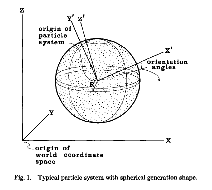
shape => a region of newly born random particles about its origin
lifetime
A particle's initial color, transparency and size are determined by
mean values like MeasSpeed, maximum variations like VarSpeed of below:
InitialSpeed = MeanSpeed + Rand()*VarSpeed

사용자 삽입 이미지
More complicated generation shapes based on the law of nature or on chaotic attractors have been envisioned.
    eg. streaked spherical shapes => motion-blur particles

    2.3 Particle Dynamics
    2.4 Particle Extinction
  • when a particle's lifetime reaches zero
  • when the intensity of a particle, calculated from its color and transparency, drops belowa specified threshold
  • when a particle moves more than a given distance in a given direction from the origin of its parent particle system
    2.5 Particle Rendering
        (1) Explosions and fire, the two fuzzy objects we have worekd with the most, are modeled well with the assumption that each particle can be displayed as a point light source. (Other fuzzy objects, such as clouds and water, are not.)
        (2) Since particles do not reflect but emit light, shadows are no longer a problem.
    2.6 Particle Hierarchy


3. USING PARTICLE SYSTEMS TO MODEL A WALL OF FIRE AND EXPLOSIONS
The Genesis Demo sequence from the movie Star Trek II: The Wrath of Khan was generated by the Computer Graphics project of Lucasfilm Ltd.

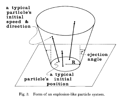
사용자 삽입 이미지
The initial direction of the particles' movement was constrained by the system's ejection angle to fall within the region bounded by the inverted cone. As particles flew upward, the gravity parameter pulled them back down to the planet's surface, giving them a parabolic motion path. The number of particles generated per frame was based on the amount of screen area covered by the particle system.
Varying the mean velocity parameter caused the explosions to be of different heights.
The rate at which a particle's color changed simulated the cooling of a glowing piece of some hypothetical material.

When a motion picture camera is used to film live action at 24 frames per second, the camera shutter typically remains open for 1/50 of a second. The image captured on a frame is actually an integration of approximately half the motion that occurred between successive frames. An object moving quickly appears blurred in the individual still frames.

    ref. Tom Duff

    cf. seed value


4. OTHER PPLICATIONS OF PARTICLE SYSTEMS
    4.1 Fireworks

posted by maetel
2007. 4. 30. 17:52 Computation/Algorithm
The term “particle system” was coined in 1983 by William T. Reeves as he worked to create the “Genesis” effect at the end of the movie, Star Trek II: The Wrath of Khan.

ref.
traer.physics

“A particle system is a collection of many many minute particles that together represent a fuzzy object. Over a period of time, particles are generated into a system, move and change from within the system, and die from the system.”
invalid-file

Willian T. Reeves <Particle Systems—a Technique for Modeling a Class of Fuzzy Objects>

ref.
Siggraph: Particle Systems
Evans & Sutherland @http://www.es.com


invalid-file

Karl Sims <Particle animation and rendering using data parallel computation>

http://doi.acm.org/10.1145/97879.97923
ref.
Karl Sims home page
wikipedia: Karl Sims

invalid-file

Alain Fournier (University of Toronto) & Don Fussell (The University of Texas at Austin) & Loren Carpenter (Lucasfilm) <Computer Rendering of Stochastic Models>

http://doi.acm.org/10.1145/358523.358553


TGLTLSBFSSP: Models
wikipedia: Particle_system
Lucasfilm Ltd. @http://www.lucasfilm.com
GenArts @http://www.genarts.com

'Computation > Algorithm' 카테고리의 다른 글

steering vector  (0) 2007.06.25
Boids  (0) 2007.06.21
Pseudo-random  (0) 2007.04.27
noise  (0) 2007.04.21
Perlin Noise  (0) 2007.04.21
posted by maetel